Power Supply Repair: Sony SLV-373UB VCR
Some time ago I purchased a VCR player to use while digitising some family video tapes. It was the rather fancy Sony SLV-373UB with on-screen menu and massive jog-wheel remote control. Shortly after I had transferred the last video from tape, the VCR player quietly died—the front panel display turned off and it stopped responding to any input. Inserting a cassette didn't prompt it to pull it in and load it. I put the machine to one side and forgot about it for a long time. Now I have unearthed more tapes to digitise and dispose of, I've been trying to get the player working again. (The new tapes aren't anything exciting — old WordPerfect training videos).
Since the VCR is quite old (I think from 1990?) with no obvious mechanical problems before the failure, I suspected the power supply. Electrolytic capacitors from the 1990s tend to have dried out or leaked after thirty years so they're a first suspect for failures that don't involve loud bangs.
Safety and notes
The usual safety warning applies here: the power supply of a VCR contains mains voltages (230V) which can injure or kill you if you get shocked by them. I recommend reading through and referring to 'Notes on the Troubleshooting and Repair of Small Switchmode Power Supplies', in particular the section on safety. Version 2.86 (2014-01-28) was current when I wrote this and it was immensely helpful.
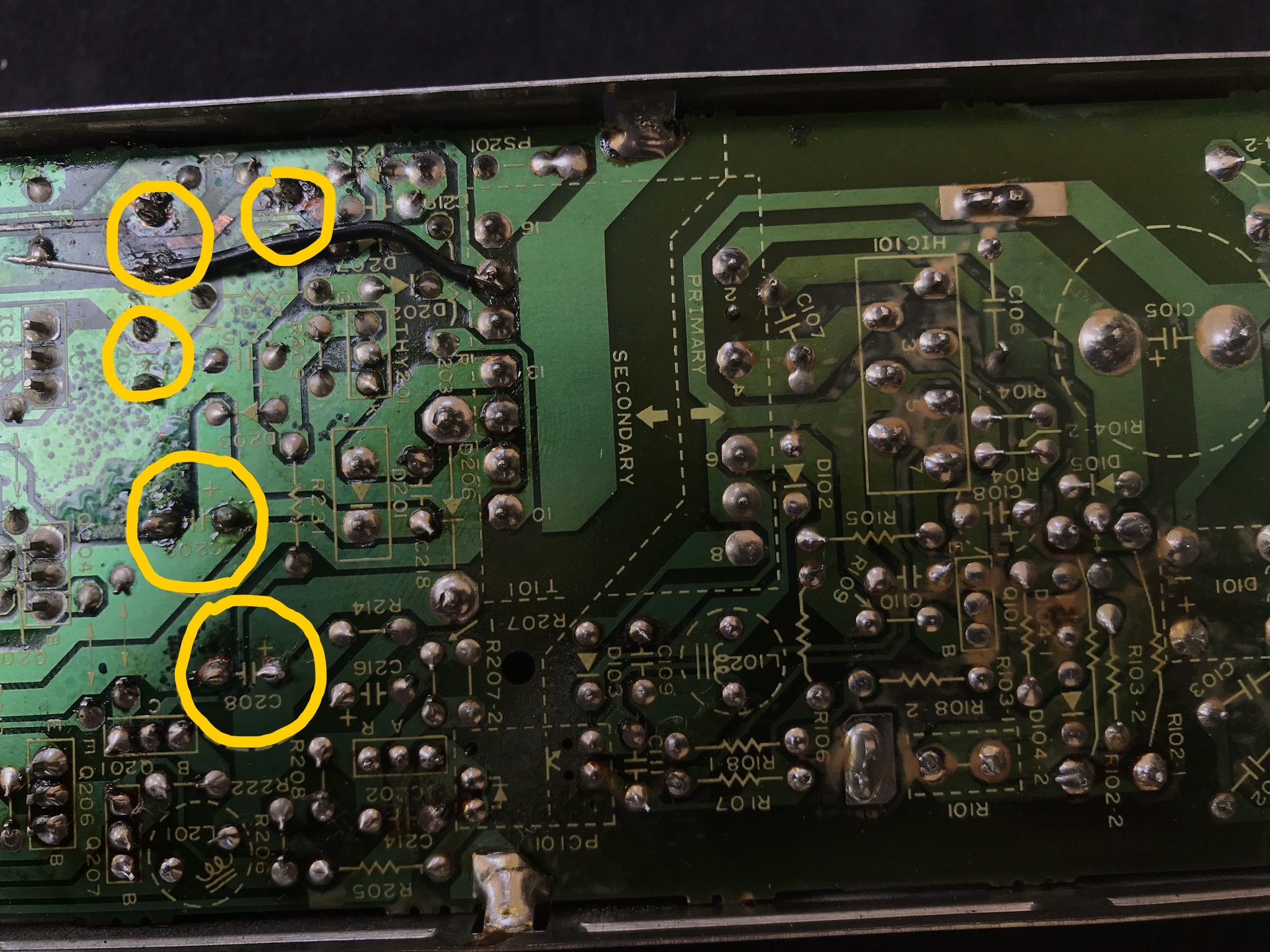
The PCB used in the power supply is panelised (where multiple boards are printed onto a larger piece of material then separated). So don't be suprised if your component designators differ from mine. All my capacitors are in the C2xx range so presumably my board was the second panel in a set.
Removing the power supply
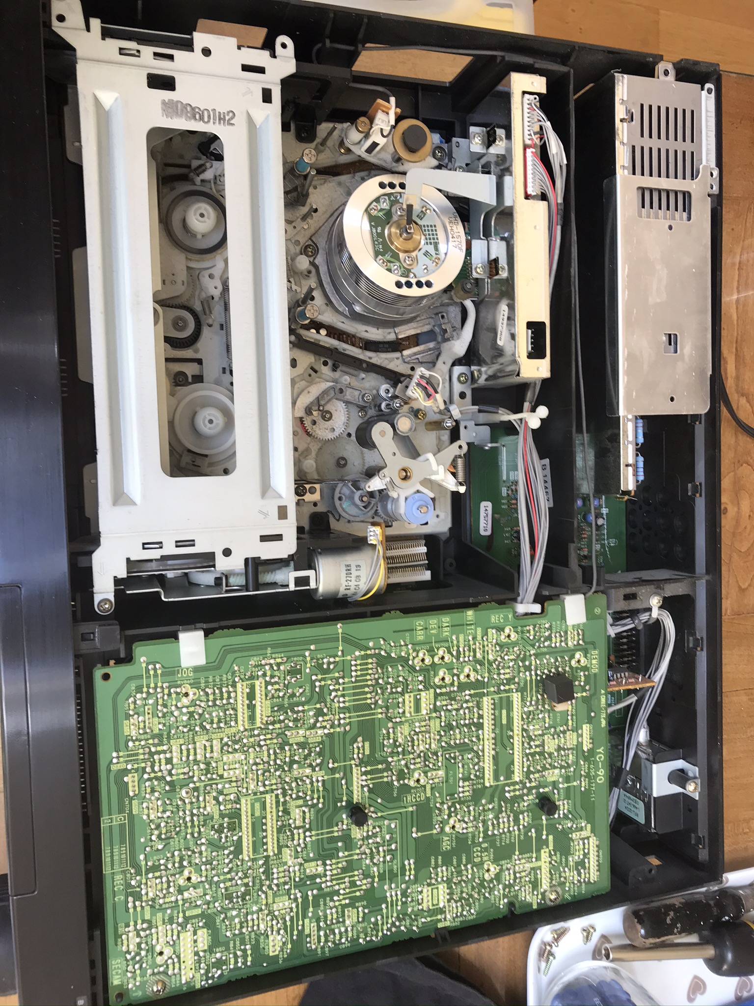
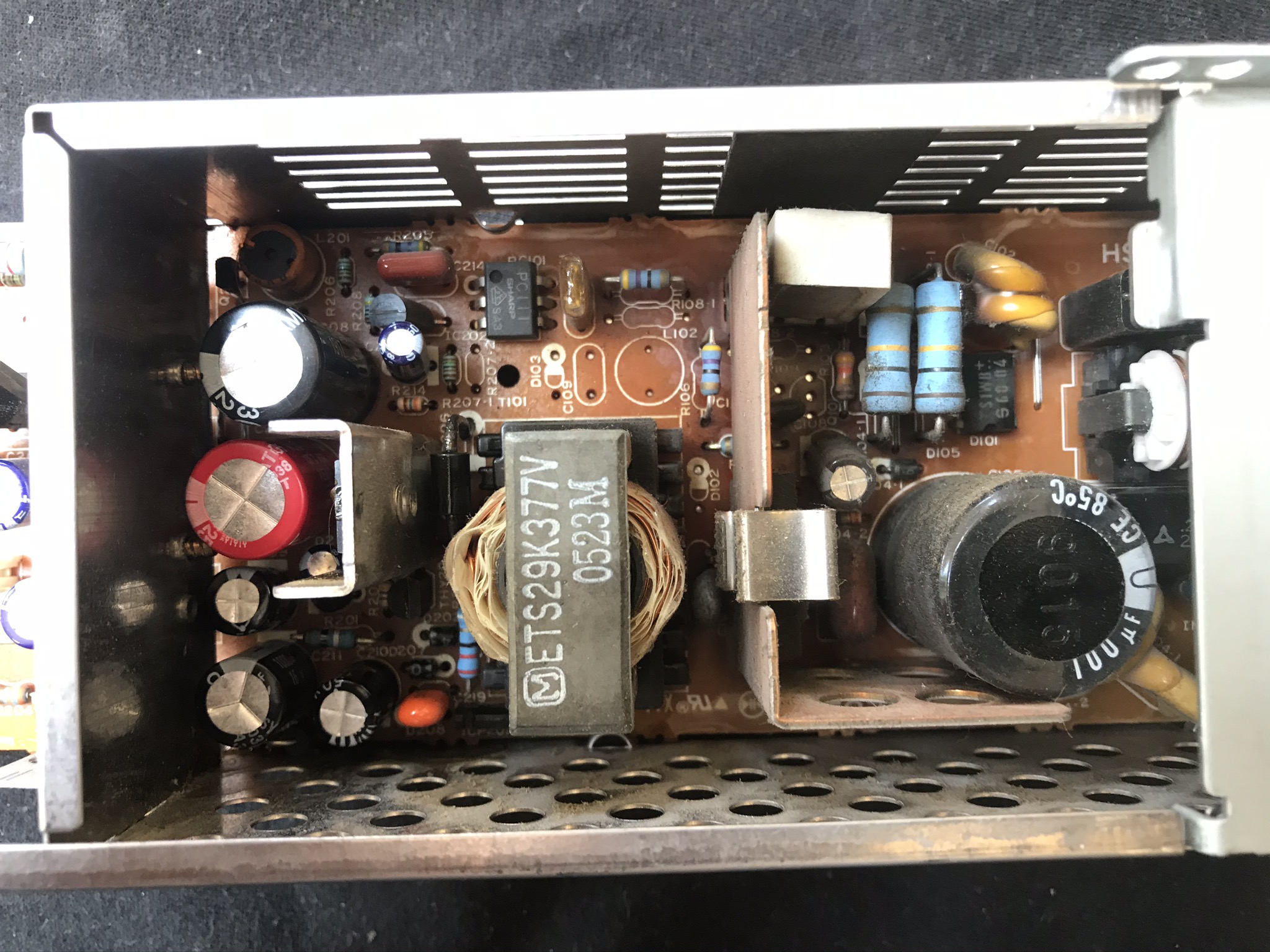
After removing the four case screws (two on the left; two on the right) we're presented with the inside of the VCR player.
Opening up the PSU
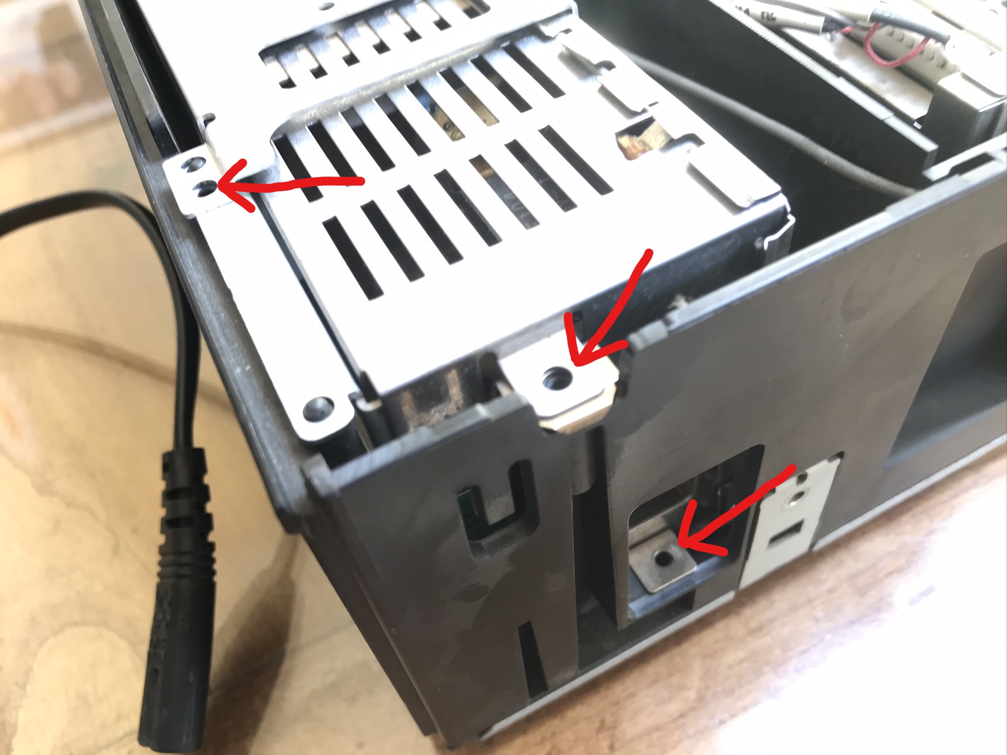
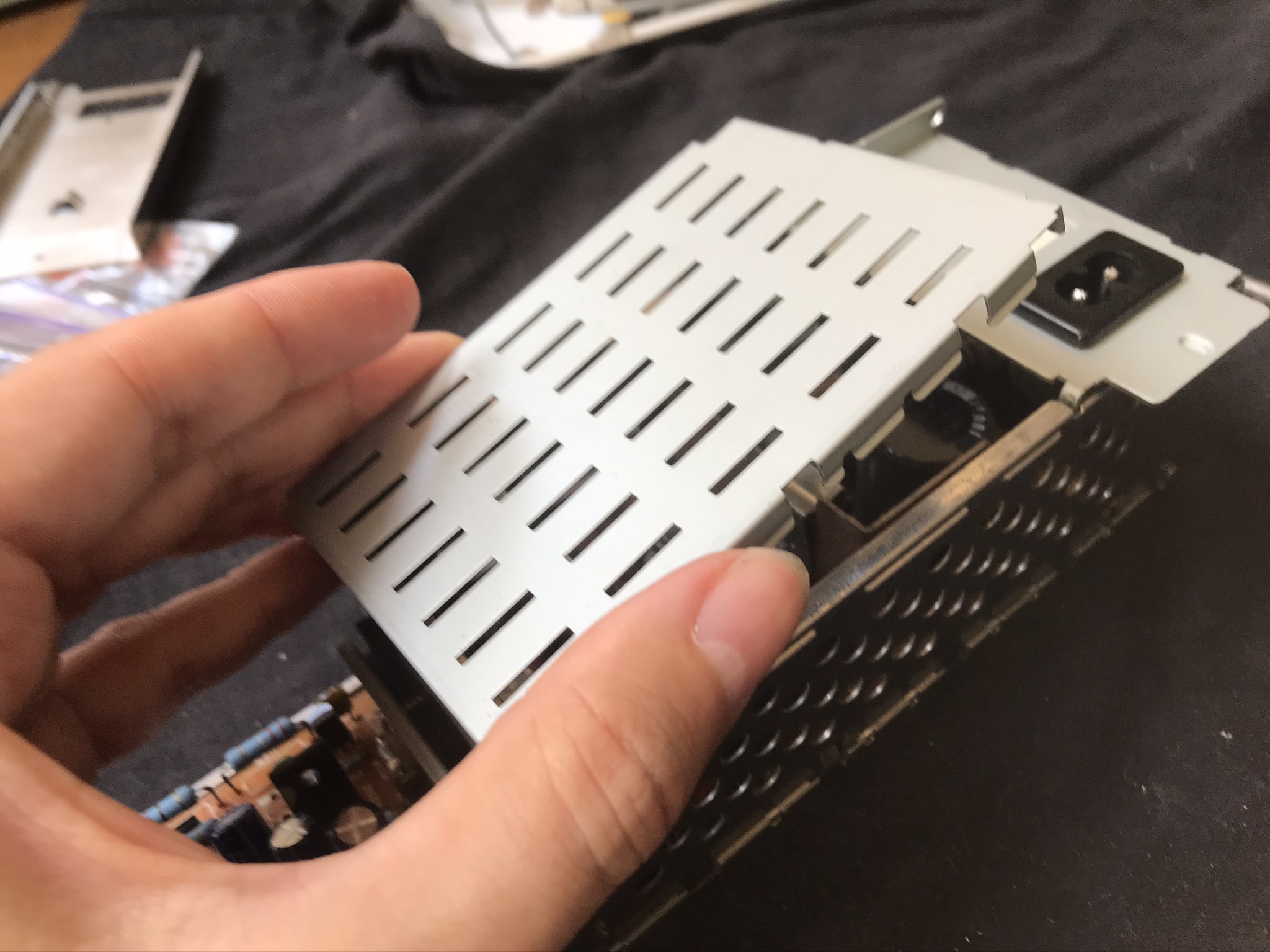
The main body of the PSU is enclosed on all sides by metal shielding. I'm guessing the analogue electronics that read the VCR tapes really don't want to be disturbed by any noise from the switching power supply. We'll need to remove them to access the guts of the PSU, but make sure not to damage them as they will need to be refitted afterwards.

Testing the outputs
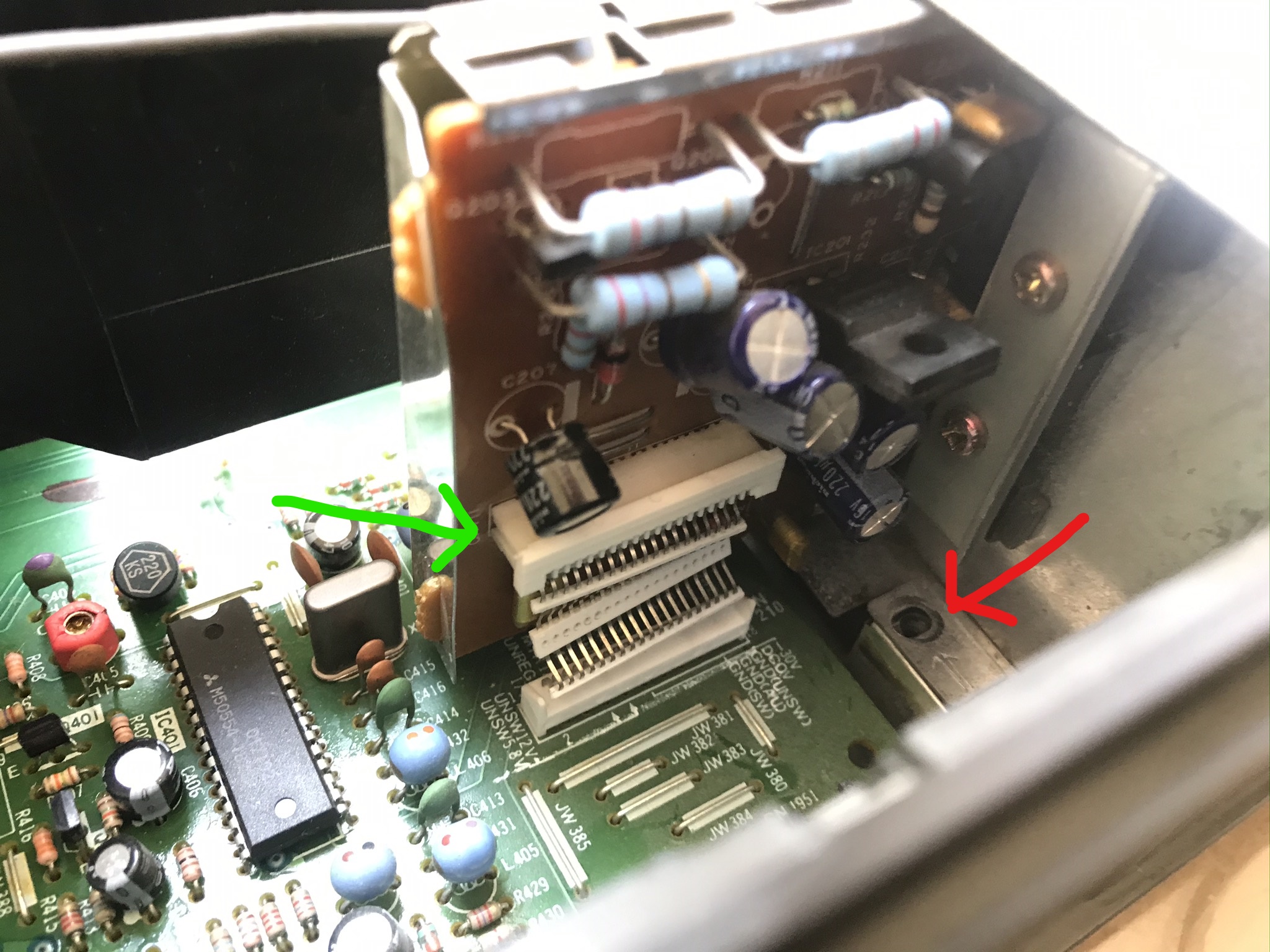
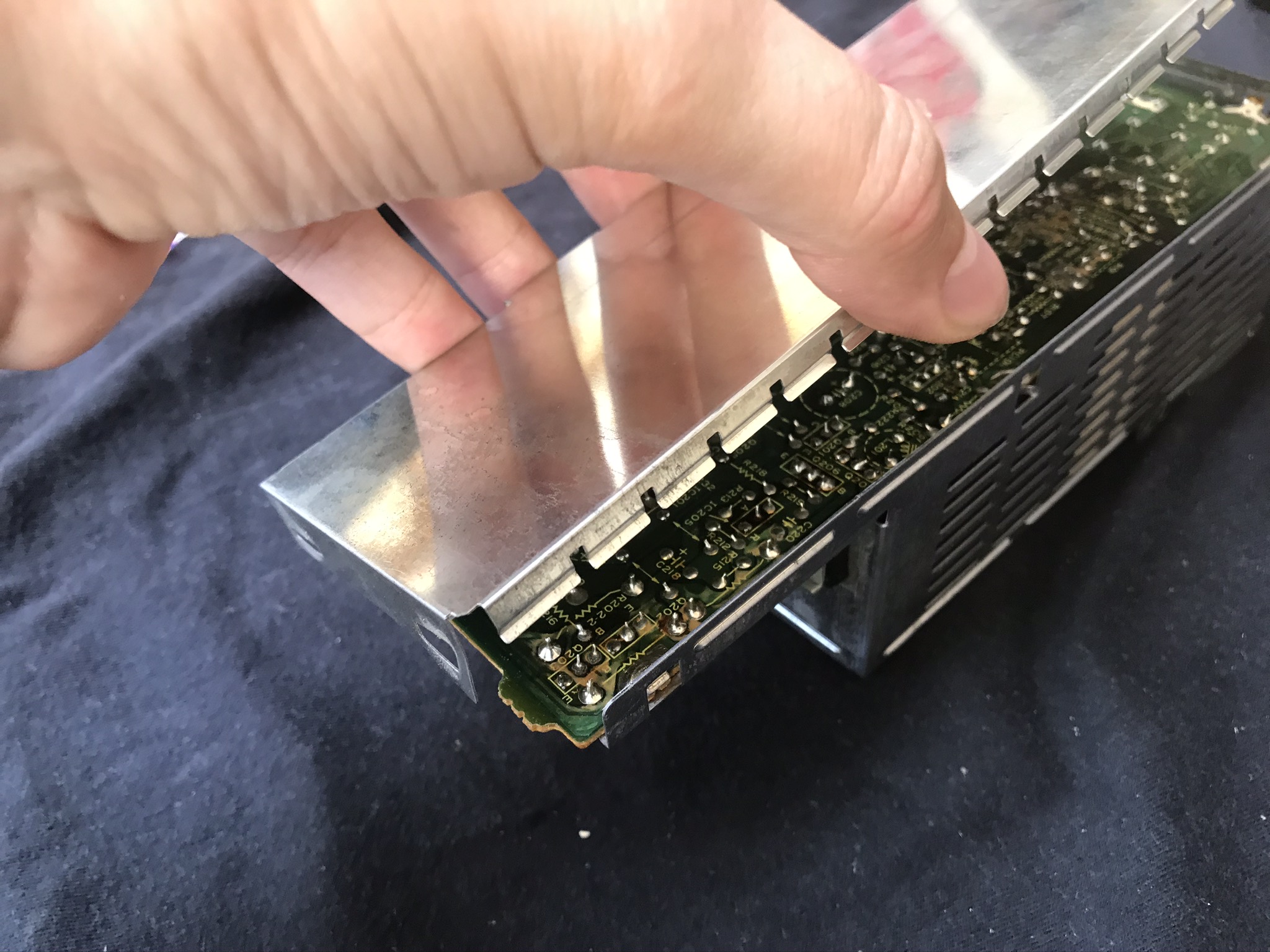
With the power supply removed and the PCB exposed I (carefully!) probed the outputs while it was plugged in and turned on. The rear of the output connector is the easiest place to do this. In case the silkscreen is hard to read, the pinout is:
| Pin | Silkscreen | Notes |
|---|---|---|
| 1 | 18V | |
| 2 | M12V | Both M12V tied together; 12V for motors? |
| 3 | M12V | |
| 4 | G | All G tied together; ground. |
| 5 | G | |
| 6 | 12V | 12V from regulator IC201. |
| 7 | 9V | 9V from regulator IC203. |
| 8 | 6V | |
| 9 | 5V | Switched from transisitor Q206. |
| 10 | G | |
| 11 | G | |
| 12 | G | |
| 13 | Not labelled on silkscreen but tied with G. | |
| 14 | G | |
| 15 | 43V | For VFD display? |
| 16 | 0V | Different from G? Switched ground perhaps? |
| 17 | 3.6V | Comes from a tiny IC and maybe separate secondary transformer coil; standby power? |
| 18 | -27V | |
| 19 | P/ON IS | Input from main VCR boards (soft power switch) |
My multimeter showed no output on any of the power rails. The large capacitor on the primary side was showing ~306V which drained to 0V within a few seconds of power being removed. Continuity tester showed no shorted components on the primary side. I wasn't really expecting any because that tends to cause the fuse to pop, but it's nice to make sure. Time to look more closely at the capacitors.
Replacing the capacitors
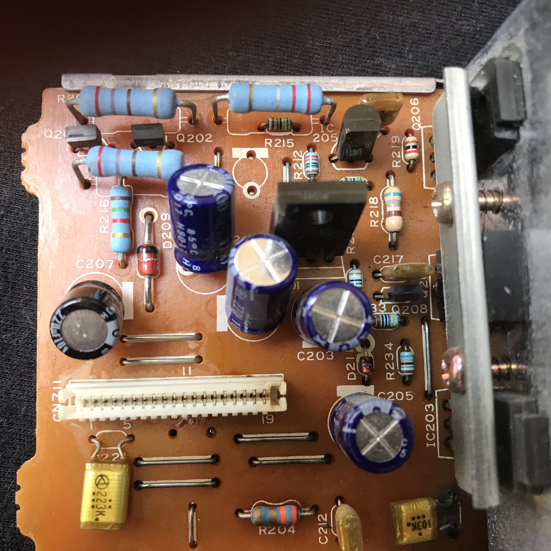
It was tricky at first to see what (if anything) was wrong with the capacitors. Close inspection with a magnifying glass showed that one of the electrolytic capacitors on the secondary side had lifted it's vent flaps and presumably dried out. If one capacitor is bad then it's likely that all of them are so I desoldered all five of the large secondary capacitors from inside the PSU. Once they were removed it became apparent that they were all leaking from their base and the brown substance coating the underside of the PCB wasn't flux residue but capacitor juice. The smaller capacitors on the outside of the PSU and the one large capacitor on the primary side didn't appear to be leaking so I left those in place.
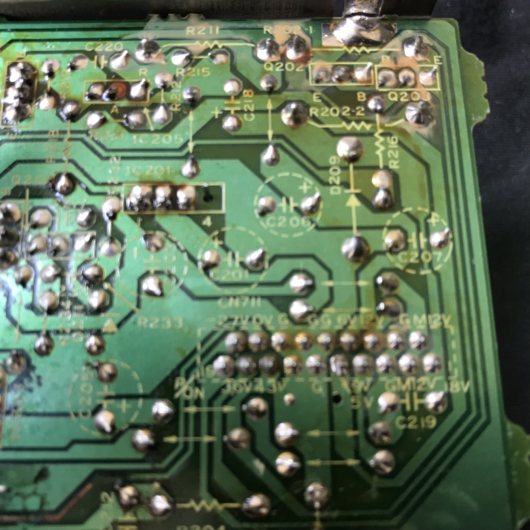
I should note that I'm not that experienced at doing this and I managed to screw up the desoldering quite badly—I didn't realise the capacitors were held together with a small amount of resin and while trying to get them out managed to lift the traces from one of the capacitors (the 0V trace going to the output connector). You can see the horrible repair I made in the picture below. Frankly this isn't my best work by far; even though it works I know I could have done better. Oh well…
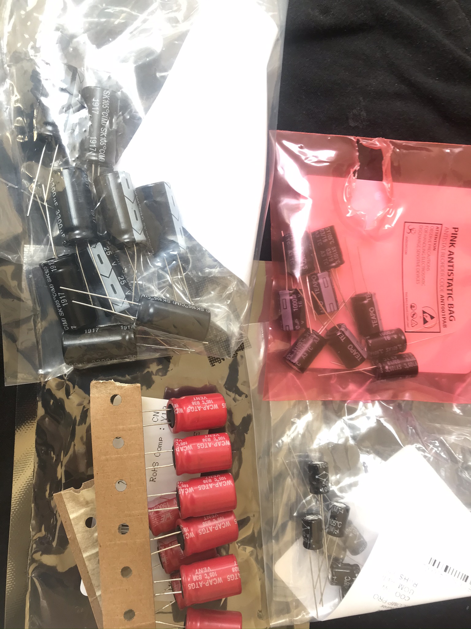
The capacitors I replaced and their values were:
| Designator | Capacitance µF | Voltage V | Temperature rating °C | Diameter mm | Height mm | Lead spacing mm |
|---|---|---|---|---|---|---|
| C202 | 1500 | 25 | 105 | 13 | 31 | 6 |
| C208 | 3300 | 10 | 105 | 13 | 33 | 5 |
| C209 | 100 | 50 | 105 | 8 | 20 | 4 |
| C210 | 100 | 50 | 105 | 8 | 20 | 4 |
| C211 | 1000 | 10 | 105 | 10 | 21 | 6 |
Ratings were read off the removed capacitors; sizes were measured by hand (and not particularly accurately). I managed to get replacements that met all the values but were slightly shorter in height.
Success
After replacing the capacitors (and fixing the lifted track) I fired it up again. The multimeter showed all voltages were present and mostly within 10% (without any load on the PSU I didn't expect it to be anywhere close to nominal). The 5V and 9V outputs weren't present, but I think those might be switched by the input from the VCR power button.
The large input capacitor was still showing ~306V but now when the mains was disconnected it dropped to ~26V and then slowly drained to 0V over the next few minutes. That seems like better behaviour than draining to 0V nearly instantly as before.
I placed the PSU back into the chassis and connected it up to the VCR. With fingers crossed I turned it on and — success! The VFD display turned on with a blinking 12:00 and the tape head spun briefly. It's working again!